wf3cte
The charge transfer efficiency (CTE) of the UVIS detector has inevitably been declining over time as on-orbit radiation damage creates charge traps in the CCDs. Faint sources in particular can suffer large flux losses or even be lost entirely if observations are not planned and analyzed carefully. The CTE loss will depend on the morphology of the source, the distribution of electrons in the field of view (from sources, background, cosmic rays, and hot pixels) and the population of charge traps in the detector column between the source and the transfer register. And the magnitude of the CTE loss increases continuously with time as new charge traps form.
CTE is typically measured as a pixel-transfer efficiency, and would be unity for a perfect CCD. One indicator of CTE is the Extended Pixel Edge Response (EPER). Inefficient transfer of electrons in a flat-field exposure produces an exponential tail of charge in the overscan region. Analysis of monitoring observations through January 2013 shows that CTE continues to decline linearly over time (WFC3 ISR 2013-03).
The CTE correction step uses it’s own dark reference files which have themselves been corrected for CTE. The specific reference file used for any dataset may be found in the image header keyword DRKCFILE. This step also uses a special bias reference file as part of the CTE correction itself, referred to in the header by the BIACFILE keyword. This BIACFILE is only used to facilitate the CTE correction, the resulting corrected image then uses the normal BIASFILE to correct the science frame after the CTE correction has been performed. After the CTE correction has been performed and the data progresses through the rest of the pipeline, the special CTE corrected dark, DRKCFILE in the header, will be used for the dark current correction instead of the DARKFILE.
There is a PCTETAB refrence file which contains extensions of calibration images and tables of parameters used during the CTE correction stage. The header of this file also contains parameters for the CTE correction algorithm. These parameters, and important scalars which are used to correct the data are stored in the output image headers. Users who wish to use other settings for the CTE correction algorithm can adjust the pertinent keywords in their dataset header and calwf3 will show them preference. See the http://www.stsci.edu/hst/wfc3/documents/ISRs UVIS2.0 reference ISR or Cookbook for more information.
wf3cte performs the CTE correction on raw data files. The calibration step keyword is PCTECORR, if this is set to PERFORM then the CTE correction will be applied to the dataset. Some caveats for its use:
- CTE corrections can ONLY be performed on RAW data which has not been calibrated in any way.
- Data which have already been through BLEVCORR, BIASCORR or DARKCORR will be rejected.
- The CTE correction step in the pipeline is implemented for FULL FRAME images only in v3.3, but v3.4 will also correct the CTE in the following subarray apertures, the primary distinction being that these apertures have physical overscan pixels included which are used to calculate a secondary bias subtraction for the image before the CTE is measured; a future version of
calwf3may enable CTE corrections for the remaining subarrays which don’t have physical overscan pixels, but is still being validated by the science team.
UVIS1-2K2A-SUB
UVIS1-2K2B-SUB
UVIS2-2K2C-SUB
UVIS2-2K2D-SUB
UVIS2-C1K1C-SUB
UVIS2-C512C-SUB
UVIS2-C512D-SUB
UVIS1-C512A-SUB
UVIS1-C512B-SUB
UVIS1-2K4-SUB
UVIS-QUAD-SUB
UVIS2-2K4-SUB
The standalone call will produce a RAC fits file by default. This contains only the CTE corrected data, no other calibrations have been performed.
For more information the the WFC3 CTE please see the WFC3 CTE webpage .
Running wf3cte from a python terminal
In Python without TEAL:
>>> from wfc3tools import wf3cte
>>> wf3cte(filename)
In Python with TEAL:
>>> from stsci.tools import teal
>>> from wfc3tools import wf3cte
>>> teal.teal('wf3cte')
In Pyraf:
>>> import wfc3tools
>>> epar wf3cte
Displaying output from wf3ccd in a Jupyter Notebook
When calling wf3cte from a Jupyter notebook, informational text output from the underlying wf3cte.e program will be passed through print as the calibration runs by default, and show up in the user’s cell. This behavior can be customized by passing your own function as the log_func keyword argument to wf3cte. As output is read from the underlying program, the wf3cte Python wrapper will call log_func with the contents of each line. (print is an obvious choice for a log function, but this also provides a way to connect wf3cte to the Python logging system by passing the logging.debug function or similar.)
If log_func=None is passed, informational text output from the underlying program will be ignored, but the program’s exit code will still be checked for successful completion.
Parameters
- input : str
- Name of input files
- a single filename (
iaa012wdq_raw.fits)- a Python list of filenames
- a partial filename with wildcards (
\*raw.fits)- filename of an ASN table (
\*asn.fits)- an at-file (
@input)-1 : value, as in minus one, this will make sure only 1 processor/thread is used during processing, otherwise all available are used.
- verbose: bool, optional
- Print verbose time stamps?
The wf3cte function can also be called directly from the OS command line:
>>> wf3cte.e input [-options]
Where the OS options include:
- -v: verbose
- -1: turn off multiprocessing
Basic Steps In The CTE Correction
- The reference bias image named in the BIACFILE header keyword is subtracted from the data
- Parameters from the CTE parameter table, referenced in the PCTETAB header keyword, are read and stored
- The data is reformatted so that each quadrant has been rotated such that the readout amp is located at the lower left of the array. The reoriented four quadrants are then arranged into a single 8412x2070 image (including the overscan pixels) with amps CDAB in that order. In this format, the pixels are all parallel-shifted down, then serial-shifted to the left
- An additional bias correction is performed using the residual bias level measured for each amplifier from the steadiest pixels in the horizontal overscan, this value is then subtracted from all the pixels in each respective amp
- The image is corrected for gain
- The smoothest image that is consistent with being the observed image plus read-noise is found and subtracted. This is necessary because we want the CTE correction algorithm to produce the smoothest possible reconstruction, consistent with the original image and the known read-noise. The algorithm then constructs a model that is smooth where the pixel-to-pixel variations aren’t too large. It respects the pixel values, using a 2-sigma threshold to mitigate read-noise amplification, and iteration is not done when the deblurring is less than the read-noise.
- The CTE correction itself is calculated and then subtracted from the original, raw, uncorrected and uncalibrated image.
- The corrected image is now ready to continue through the rest of the pipeline. When the DARKCORR header keyword is set to perform, the CTE corrected image will use the dark reference file referred to in the DRKCFILE header keyword.
- In the case of subarray image, the same steps are performed as above after the image has been placed into the correct full-frame reference position since the correction is dependent on the distance of the pixels away from the read-out amplifier.
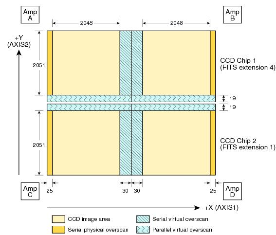
Figure 1: UVIS data raw full-frame file format
The PCTETAB and Algorithm Parameters
The following are new primary header keywords which will be updated in the data headers during the wf3cte step. They are also specified in the PCTETAB reference file.
| KEYWORD | DESCRIPTION |
|---|---|
| CTE_NAME | name of cte algorithm [string] |
| CTE_VER | version number of cte algorithm [string] |
| CTEDATE0 | date of wfc3/uvis installation in HST, in modified Julian days (MJD) |
| CTEDATE1 | reference date of CTE model pinning, in modified Julian days (MJD) |
| PCTETLEN | max length of CTE trail |
| PCTERNOI | read-noise amplitude for clipping |
| PCTENFOR | number of iterations used in CTE forward modeling |
| PCTENPAR | number of iterations used in the parallel transfer |
| PCTENSMD | read-noise mitigation algorithm |
| PCTETRSH | over-subtraction threshold |
| PCTEFRAC | cte scaling frac calculated from expstart and used in the algorithm |
| PCTERNOI | the read-noise clipping level to use |
| FIXROCR | make allowance for readout cosmic rays |
The PCTETAB reference file has 4 extensions, two tables and two images:
Filename: wfc3_cte.fits
No.    Name         Type      Cards   Dimensions   Format
0    PRIMARY     PrimaryHDU      21   ()
1    QPROF       BinTableHDU     16   999R x 3C    ['i', 'i', 'i']
2    SCLBYCOL    BinTableHDU     20   8412R x 5C   ['i', 'e', 'e', 'e', 'e']
3    RPROF       ImageHDU        12   (999, 100)   float32
4    CPROF       ImageHDU        12   (999, 100)   float32
The first extension lists the charge-trap levels, the columns are respectively the trap number, the charge-packet size it applies to (in electrons), and the size of the trap (also in electrons).
The second extension contains the CTE scalings as a function of column number. There are 5 columns, each with 8412 elements. The first column contains the integer column number in the amp readout-aligned large array. The other columns contain the CTE scaling appropriate for that column at the 512th, 1024th, 1536th and 2048th rows respectively.
The third extension contains the differential CTE trail profile as a function of charge level in the form of an image
The fourth extension contains the cumulative CTE trail profile as a function of charge level, also in the form of an image.
Output Files
If you are running the separate wf3cte.e step a _rac.fits file will be output. This the same as a _raw.fits file except the CTE correction has been applied to the data.
If the PCTECORR step is set to PEFORM:
- when the _raw.fits file enters
calwf3, then no intermediate _rac.fits file will be saved, unless you specify the-sflag, which instructscalwf3.eto save all intermediate files. - the
calwf3pipeline will produce both CTE calibrated product and non-CTE calibrated products. The CTE products have a ‘c’ at the end of their extension name, such as _blc, _rac, _crc, _flc, and the non-CTE calibrated products contain the familiar : _blv, _crj, _flt.